week 6
This week's assignment was to create a circuit that has an input and an output, to make a capacitance-based sensor, and to create a CAD file for CNC milling next week.
tilt sensor circuit
This circuit is one of the first steps towards my final project: I learned how to use a gyroscopic sensor (MPU 6050) and made it so that a certain range of tilt would cause a green LED to light up. If the readings are out of range, a red LED lights up. It took me a moment to familiarize myself with the arduino library for the MPU, and also to make it so that my code did not have delays. My accelerometer was already correctly calibrated with m/s readings for instantaneous velocity and with tilt in radians. My red light lights up between -5 and 5 radians.
code
#include <Adafruit_MPU6050.h>


Adafruit_MPU6050 mpu;
Adafruit_Sensor *mpu_temp, *mpu_accel, *mpu_gyro;


unsigned long oldMillis = 0;
const long interval = 100;

int Green = 25;
int Red = 32;


void setup(void) {
  Serial.begin(115200);
  pinMode(Green, OUTPUT);
  digitalWrite(Green, LOW);
  pinMode(Red, OUTPUT);
  digitalWrite(Red, LOW);


  while (!Serial)
    delay(10); // will pause Zero, Leonardo, etc until serial console opens

  Serial.println("Adafruit MPU6050 test!");


  if (!mpu.begin()) {
    Serial.println("Failed to find MPU6050 chip");
    while (1) {
      delay(10);
    }
  }

  Serial.println("MPU6050 Found!");
  mpu_temp = mpu.getTemperatureSensor();
  mpu_temp->printSensorDetails();

  mpu_accel = mpu.getAccelerometerSensor();
  mpu_accel->printSensorDetails();

  mpu_gyro = mpu.getGyroSensor();
  mpu_gyro->printSensorDetails();
}


void loop() {

 unsigned long currentMillis = millis();

  if (currentMillis - oldMillis >= interval) {
   oldMillis = currentMillis;

    sensors_event_t a, g, temp;
    mpu.getEvent(&a, &g, &temp);

   sensors_event_t accel;
   sensors_event_t gyro;
 //  sensors_event_t temp;
   mpu_temp->getEvent(&temp);
   mpu_accel->getEvent(&accel);
   mpu_gyro->getEvent(&gyro);


   if ((accel.acceleration.x) > 5){
   digitalWrite (Green, HIGH);
   digitalWrite (Red, LOW);}

    else if ((accel.acceleration.x) < -5){
    digitalWrite (Green, HIGH);
    digitalWrite (Red, LOW); }

    else {
    digitalWrite (Red, HIGH);
    digitalWrite (Green, LOW);
    }

 Serial.print("Acceleration X: ");
    Serial.print(a.acceleration.x);
    Serial.print(", Y: ");
    Serial.print(a.acceleration.y);
    Serial.print(", Z: ");
    Serial.print(a.acceleration.z);
    Serial.println(" m/s^2");

    Serial.print("Rotation X: ");
    Serial.print(g.gyro.x);
    Serial.print(", Y: ");
    Serial.print(g.gyro.y);
    Serial.print(", Z: ");
    Serial.print(g.gyro.z);
    Serial.println(" rad/s");

   // Serial.print("Temperature: ");
   // Serial.print(temp.temperature);
   // Serial.println(" degC");

    Serial.println("");


  }

}
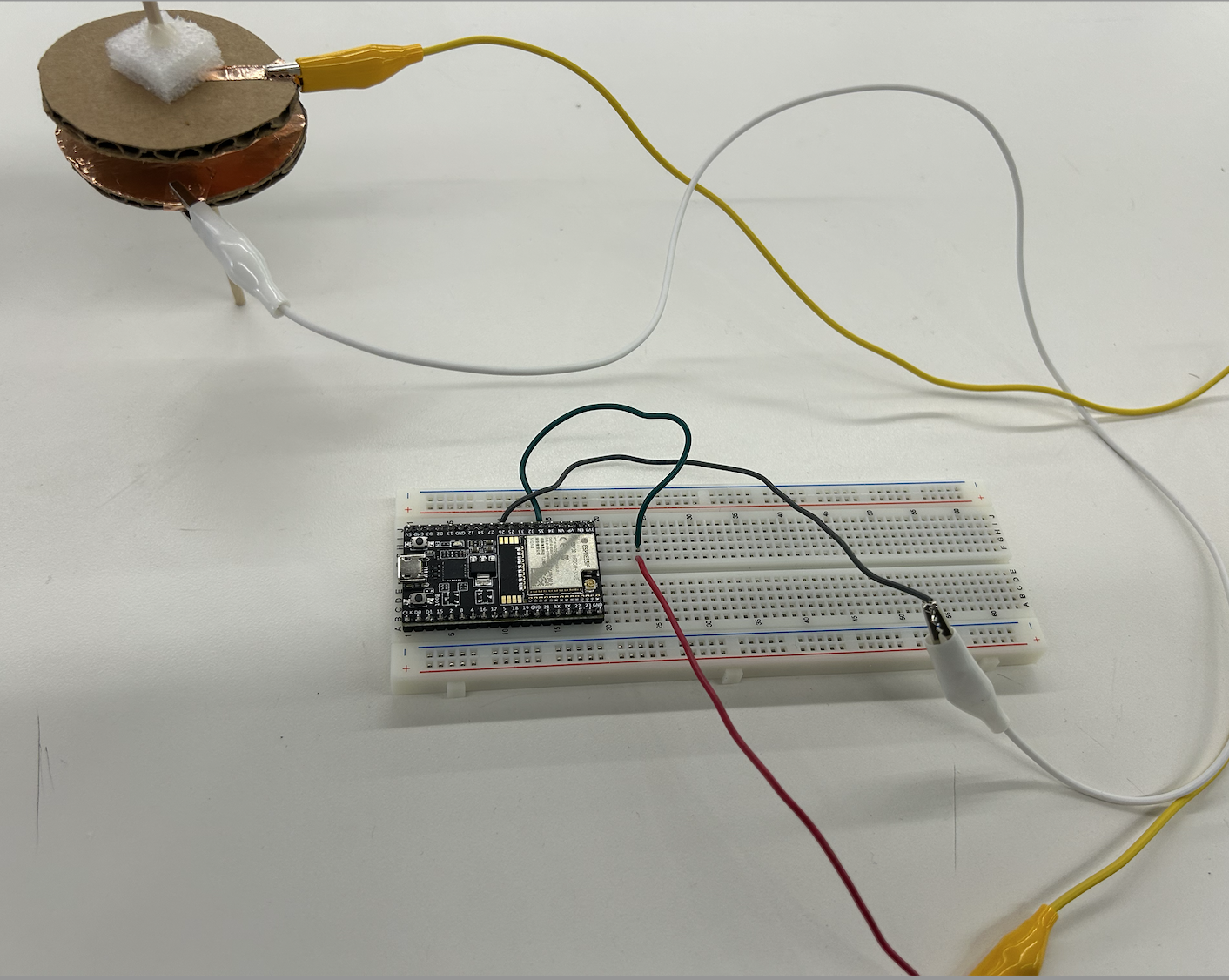
capacitance-based angle sensor
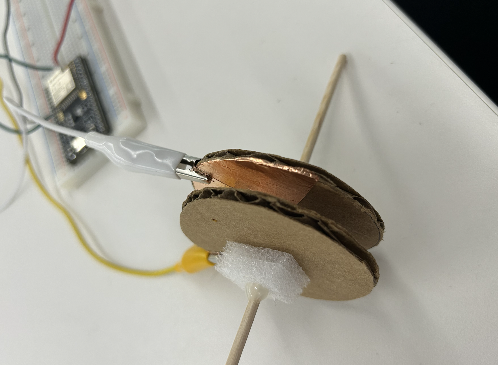
The capacitance sensor itself was not too difficult to make. I cut two circles out from cardboard and put a semi-circle of copper sticker on each one. With some styrofoam and some hot glue, I fixed the distance between the two "plates". With two alligator clips, I connected the copper plates to 5v and pin 26. My analog read pin was connected to pin 35.
It turns out that callibrating the sensors to output the angle at which the upper plate has been turned is incredibly difficult. I got stuck on the calibration step——although I get readings from my sensor that reflect changes in angle (ie, when the plates have the most overlapping area the readings are maximized; when they don't overlap they are minimized), I had a really hard time making it so that they read from 0-180 degrees. With some simple math, I did find that the relationship between the angle of rotation and the capacitance reading is linear, since the overlapping area is a linear relationship to the degree of rotation. The relationship is (pi*r^2)*((pi-theta)/pi) if theta is in radians. However, I did not end up using this formula to calculate the angle since there was so much noise in the readings. Instead, knowing the angle and readings were a linear relationship, I took the subtracted the full and zero overlap readings from each other. I then took that value, subtracted it from the sum (so that the baseline reading is 0) and then divided by a constant so that my max value was 180 degrees. With a lot of trial and error, I was able to get the sensor to work and output how much one copper plate was rotated with respect to the other.
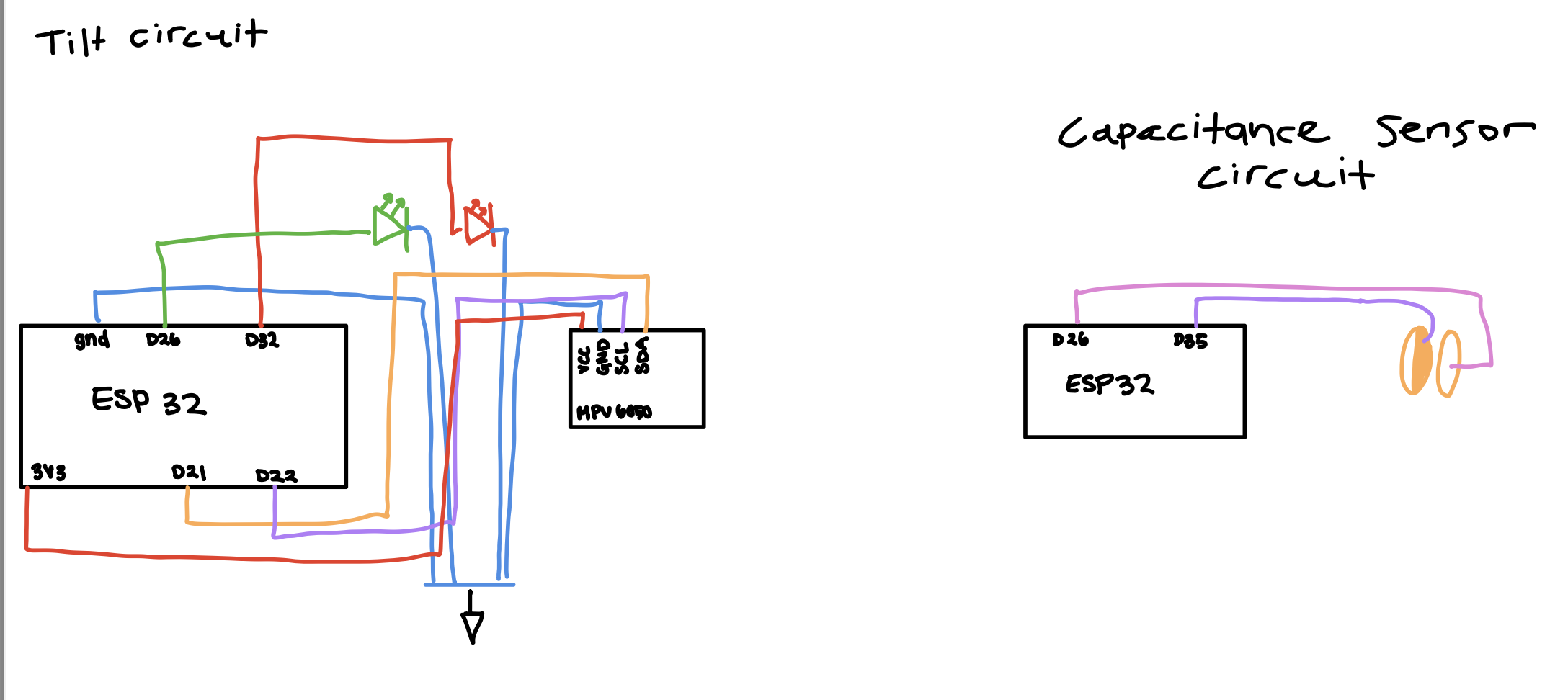
schematics and code
long result;   //variable for the result of the tx_rx measurement.
int analog_pin = 35;
int tx_pin = 26;

void setup() {
    pinMode(tx_pin, OUTPUT);      //Pin 4 provides the voltage step
    Serial.begin(9600);
}

void loop() {
    result = tx_rx();
    Serial.println(result);
}


long tx_rx(){         // Function to execute rx_tx algorithm and return a value
                      // that depends on coupling of two electrodes.
                      // Value returned is a long integer.
  int read_high;
  int read_low;
  int diff;
  long int sum;
  int N_samples = 100;    // Number of samples to take.  Larger number slows it down, but reduces scatter.

  sum = 0;

  for (int i = 0; i < N_samples; i++){
   digitalWrite(tx_pin,HIGH);              // Step the voltage high on conductor 1.
   read_high = analogRead(analog_pin);     // Measure response of conductor 2.
   delayMicroseconds(100);                 // Delay to reach steady state.
   digitalWrite(tx_pin,LOW);               // Step the voltage to zero on conductor 1.
   read_low = analogRead(analog_pin);      // Measure response of conductor 2.
   diff = read_high - read_low;            // desired answer is the difference between high and low.
   sum += diff;                            // Sums up N_samples of these measurements.
 }
  return (sum-72,000)/66.6;

}
cnc milling design
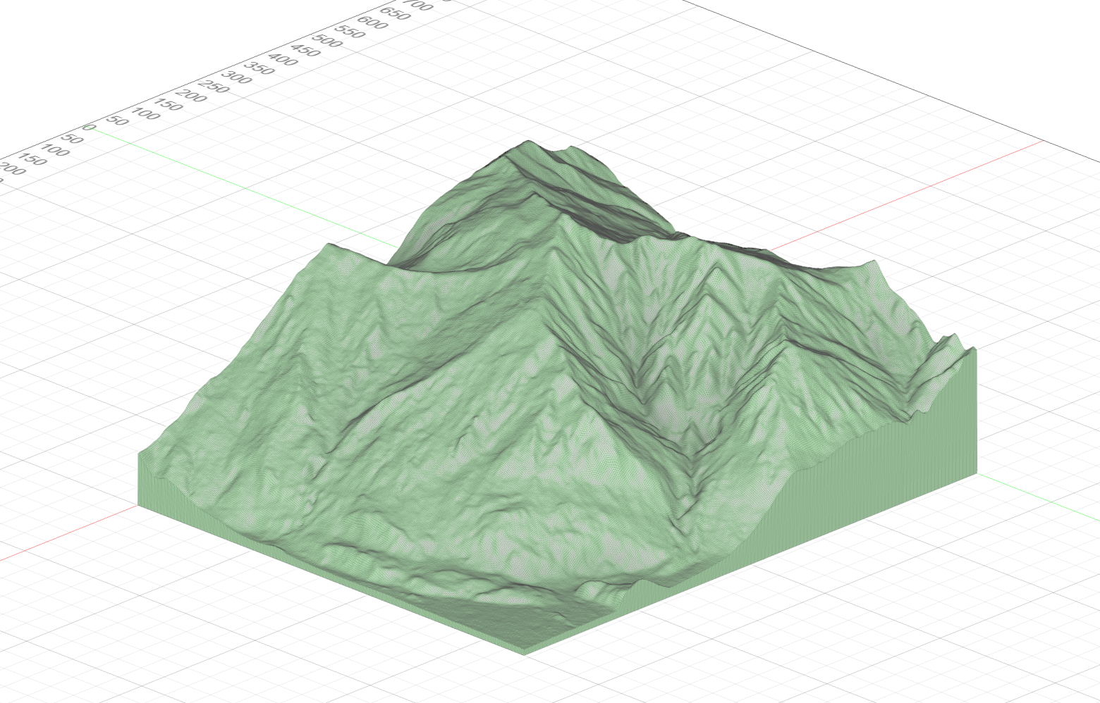
I originally planned to make a file organizer for my desk—-I was halfway done with the CAD files before I realized I could come up with the same exact product using a laser cutter. In order to fully take advantage of CNC capabilities, I decided to make something that incorporated mountain ranges. I had zero clue what I was going to make, but got started nonetheless.
Using touch terrain, I scanned my favorite mountain, Treble Cone, and imported the STL file to Fusion 360
I considered trying to make bookends, but the mountain doesn't naturally taper off in an aesthetically pleasing way. My roommmate suggested I use the valleys to make a chip and dip bowl, and though that would be super cool, it would not be very functional.
Ultimately, I couldn't come up with something I was super excited about. I'm tabling the mountain idea for now, and instead pivoted to making a mancala board. It's something that I can't make with a laser cutter, and will be a lot nicer made out of wood compared to plastic.
Download my mancala STL file