week 7
My main focus this week was creating a minimum viable project. Last week I made a tilt sensor with an arbitrary hard-coded range of "accepted" values, showcased by a green LED when in range and a red one for readings out of range. However, this week I found that I had incorrectly callibrated the sensor so I set about fixing that first.
updating code
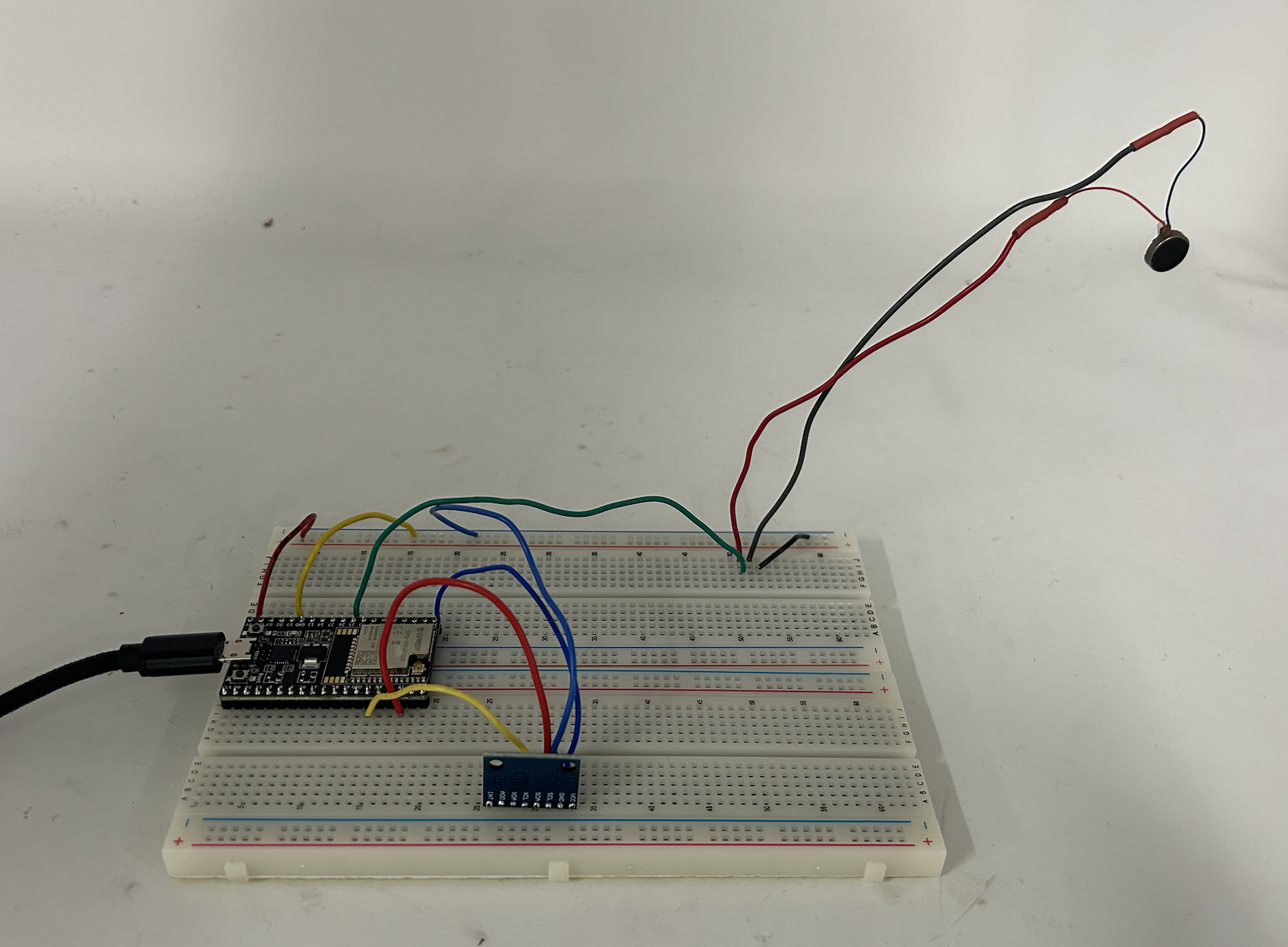
When I was fixing my callibration issues, I decided to re-solder the accelerometer with pins which allowed me to orient it perpendicular to the breadboard. I kept the LEDs as my output device in the beginning so that I could easily tell if my code ran properly with my newly configured accelerometer. To familiarize myself with the oscilloscope, I made readings which confirmed my intuiton.
As expected, the timescale of the LEDs is determined by how long they're tirggered for. This is because when I digitalWrite my LEDs to be HIGH or LOW, they hold a constant supply of 5V or are grounded.
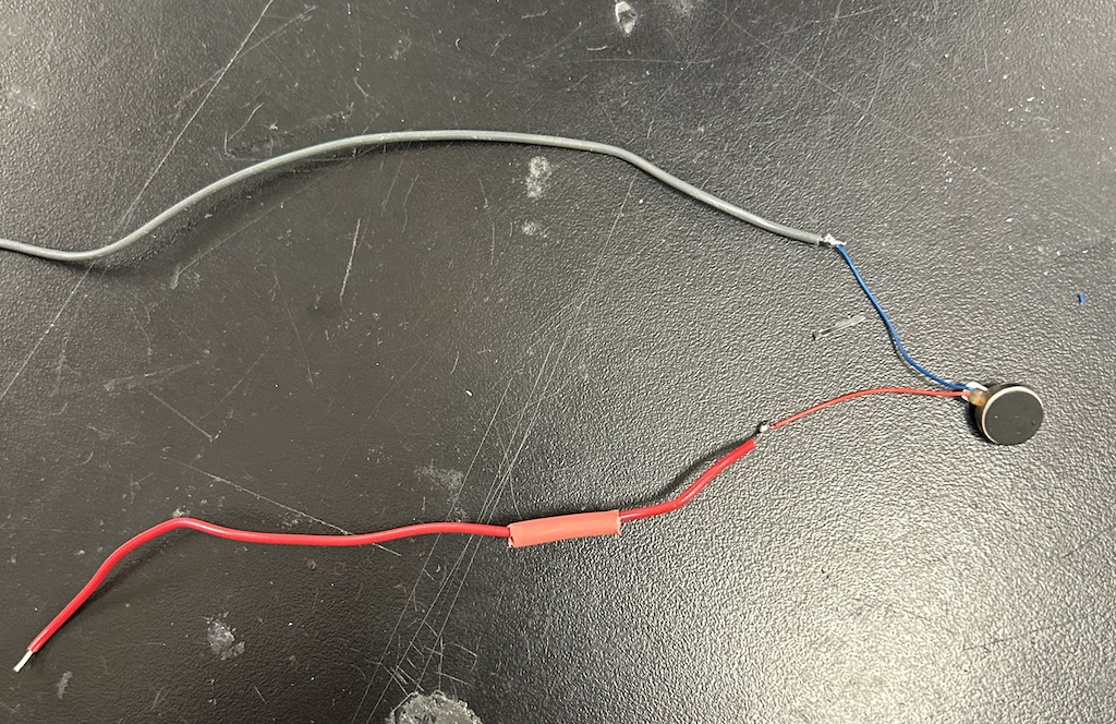
Next, I soldered a vibrating motor to wires that had large enough radii to be compatible with a breadboard. I made sure to put heat shrink around the exposed parts, and connected it to the pin I had the green LED wired to.
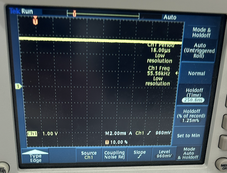
I got some pretty weird readings from the oscilloscope. While it resembles a square wave, the durations of the minimum and maximum values vary. I cannot accurately determine a timescale because of this—whatever it is, it's fast! It looks like the time scale is between 0.4 and 1 ms.
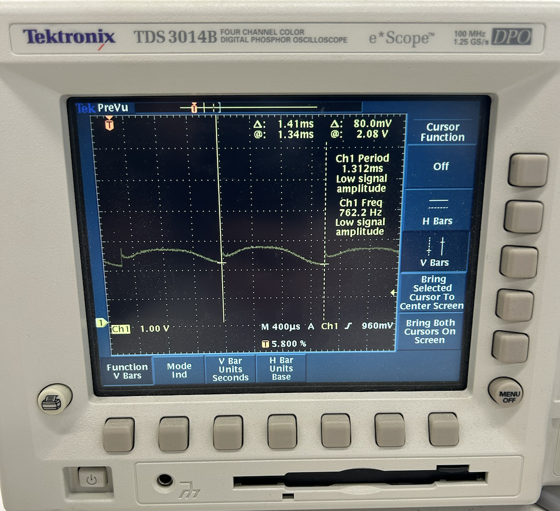
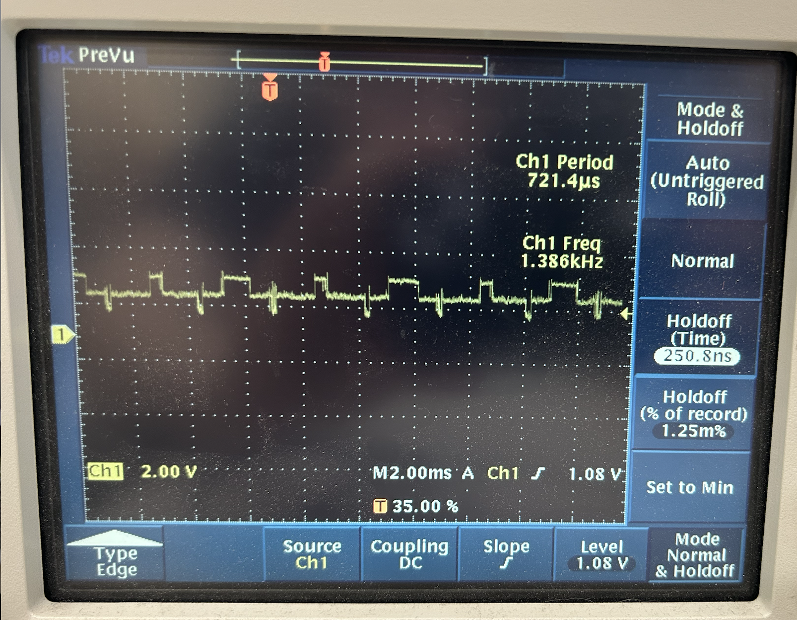
To make sure that my readings weren't a fluke, I also checked another motor. The reading for this motor looked much more conventional——the time domain had a delta of 1.4ms. So, it seems like the readings from the vibrating motor imply that the signal interacts with the vibrating motor's phase in an unconventional way!
Another change I made was making the accepted tilt values depend on the slope of the hill. For now, I've just hard-coded in scenarios. Here's one example:
 if ((mpu.getAngleX()) > 30) {

      if ((mpu.getAngleY()) > 45){
        digitalWrite (Motor, HIGH);
        }

        else if ((mpu.getAngleY()) < 30){
          digitalWrite (Motor, HIGH);
          }

        else {
          digitalWrite (Motor, LOW);
        }

  }
next steps
I found an equation for equillibrium tilt (phi) of the ski in a carved turn in this textbook, where alpha is the slope of the hill and beta is the yaw. R is the turn radius, which I'll set to 7 meters since that's the standard turn radius in slalom.
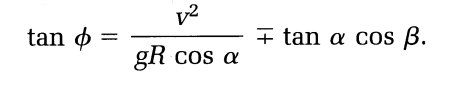
I'd like to center my range of accepted values around this equation rather than setting a general range. Since this equation relies on velocity, I'll have to find a work-around (or create a new equation for testing purposes) so that I can see if my device works without getting on snow.
Additionally, since skiing consists of connected turns and change of direction, the ski will ultimately be flat in between turns. My goal is to recognize discrete turns so that the device always gives accurate feedback. I'll implement Yaw readings to do this.
While I have configured the vibrating motors, I need to make them user friendly. I haven't yet decided whether or not I want to mount the main device on the back of the ski or the boot, and where I attatch the motors will depend on this. In order to give the least distracting sensory feedback, I'd attach the motors to either the sides of the boot or the shin depending on what is closest to the device.
If time permits, I'd like to incorporate two vibrating motors which would indicate too much or too little edge angle. Feedback from the output device on the lateral side, for example, could cue the skier to decrease the tilt of the ski.